 Loading... Please wait...
Same Day Dispatch Before 3pm
UK: Royal Mail 1st Class Recorded
NON-UK: RM International Signed
Categories
- Categories
- Security Cameras
- Security Electronics
- Tools and Others
- GAME STORAGE HDD's & MEDIA
- NINTENDO DS, DSL & DSi
- NINTENDO WII ZONE
- SONY PLAYSTATION ZONE
- VIDEO CONVERTERS
- XBOX 360 ZONE
- Gift Items
- Laptop Accessories
- WiFi
- Other DS, DSL & DSi
- Mobile Phone, iPhone, iPod & iPad
- Team Dogz Pro Stunt Scooters
- Home
- Instructions
Nintendo Wii Mod Chip Installation Instructions
 |
 |
|
|
||||
|
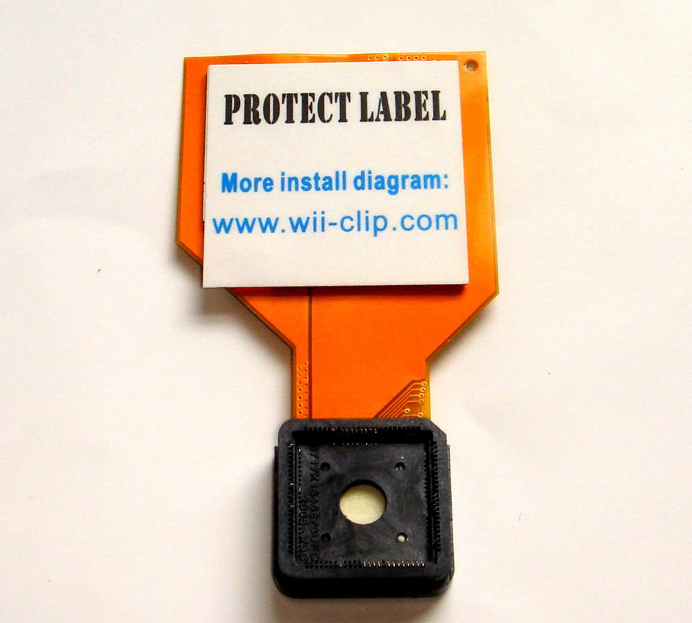
Hardwire Install Diagram Downloads & Solderless Install Diagram Forum Links
|
|||||||
 |
|
 |
 |
||||
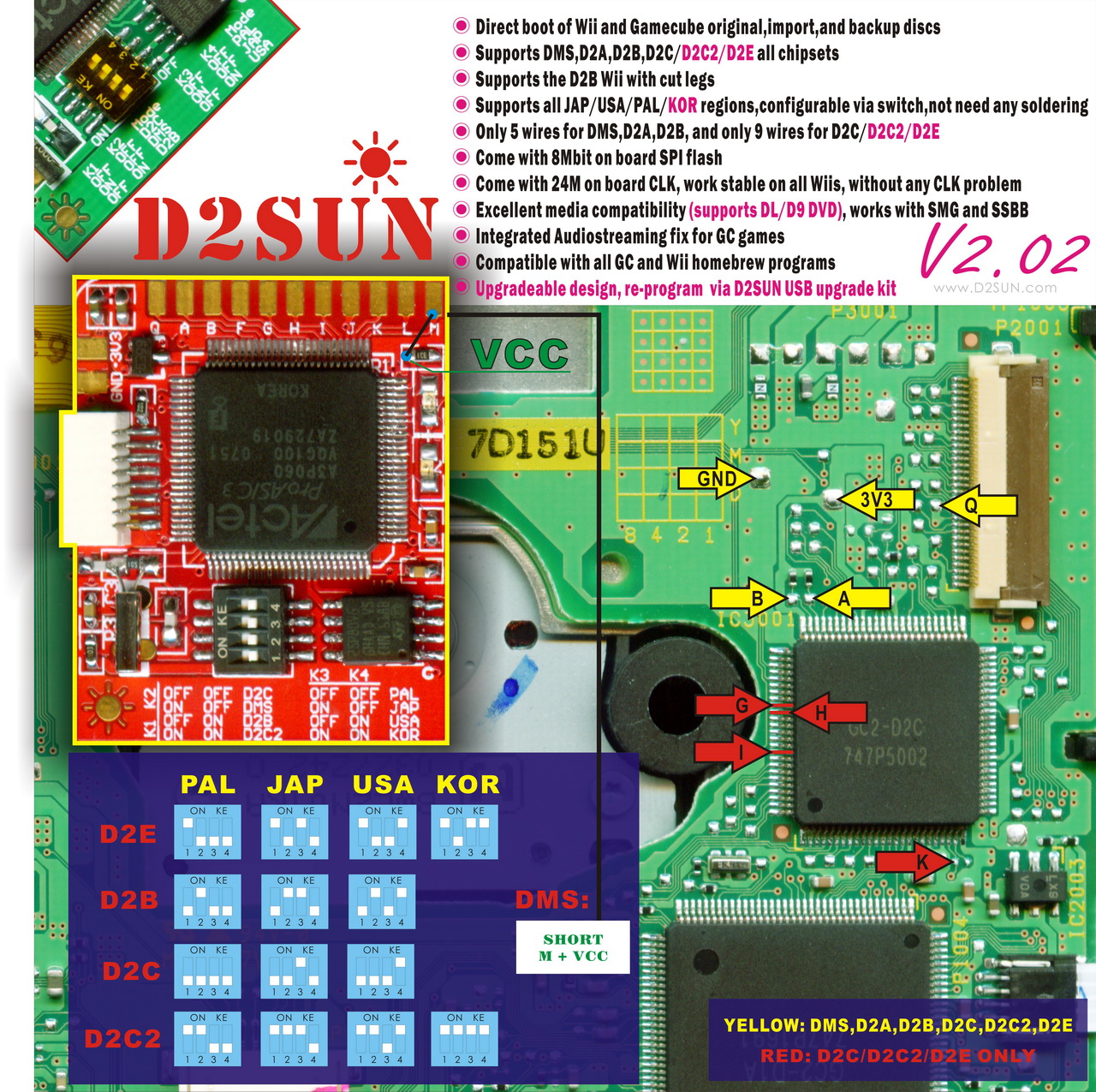
NOTE : For the WASP please use the same as D2pro 9 Wire
How to open your Wii Console, Video & Step by Step Instructions
To disassemble:
- Flip the device upside down and remove the small silver Phillips screw. Once out, remove the battery tray from the console.
- Next remove the rubber foot directly above this battery tray. Also remove the three square white stickers from the bottom of the Wii. The rubber foot and the sticker are covering hidden screws. Figure 3 provides a shot of where these screws are located.
- Unscrew the two Triwing screws and three Phillips screws from the bottom of the Wii.
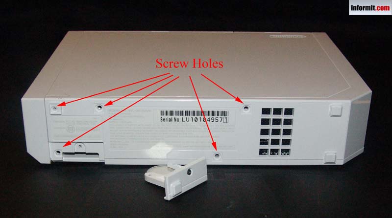
Figure 3
-
Bottom Screws
- Flip the Wii over onto its right side. Locate and remove the two rear rubber feet and the two rectangle stickers near the faceplate.
- Remove the two silver Triwing screws in the holes and remove the two black Triwing screws on the faceplate (Figure 4).
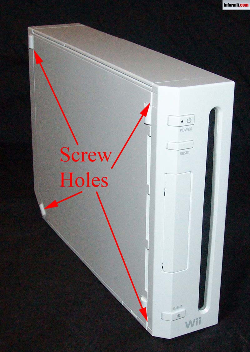
Figure 4
Left side screw locations
- Flip the Wii upright and carefully remove the two socket covers. They come right out with a little wiggling.
- Remove the three black Phillips screws from the black plate (Figure 5). Note the one closest to the faceplate is the longest and will need to go back into that hole when putting the Wii back together.
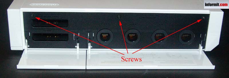
Figure 5
Top black plate screw locations
- With the screws removed, carefully pull off the faceplate of the front of the Wii. You will need to disconnect the red/black wire plug from the Wii to remove the faceplate completely. Figure 6 shows what is hiding under the faceplate.
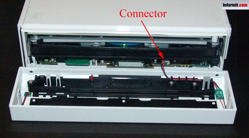
Figure 6
Under the Wii faceplate
- Remove black plate from memory/controller socket area.
- Remove two silver Phillips and two silver Triwing screws from memory/controller socket area (Figure 7).
g
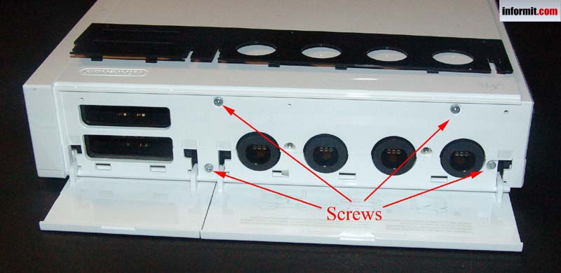
Figure 7
Topside screw locations
- Lay the Wii on left side (with the ATI and Nintendo logo facing you) and slowly work the right side cover of the console off the device. This will take a little bit of force. If something appears to be stuck, double check to ensure you removed all the screws.
- Locate and remove four screws holding DVD reader in place. Two are located in plain site in the middle of the unit. Two are located near the front of the Wii inside the DVD unit (Figure 8).
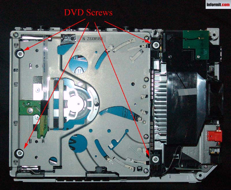
Figure 8
The insides of the Wii
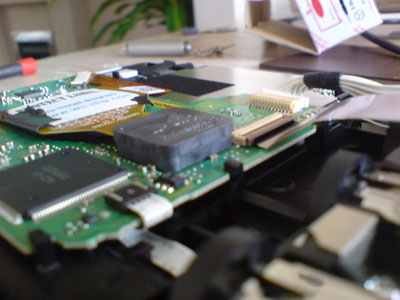
- Slowly tilt the DVD player upward toward top of Wii. There are two wires that need to be disconnected before you can safely remove the DVD unit. One is a plug type of connector that only requires a little tug. The other is a circuit strip connector that requires you to lift the brown catch, which will release the pressure holding the strip in place (Figure 9). Do not break this!
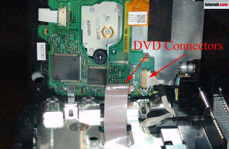
Figure 9
-
You can then access the Installation Canvas and proceed with your Wii Modification
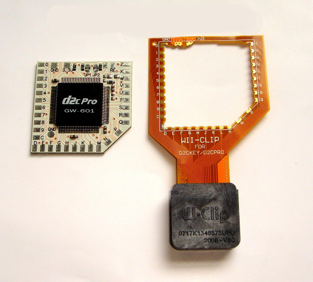

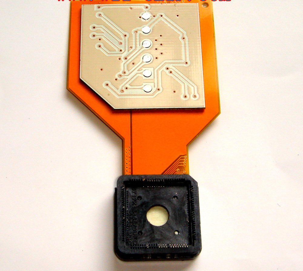

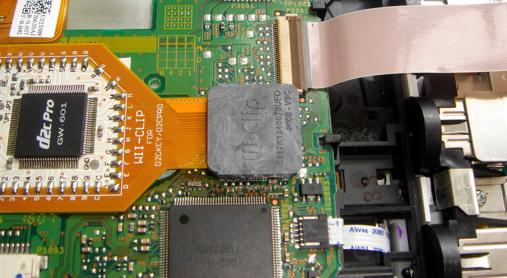


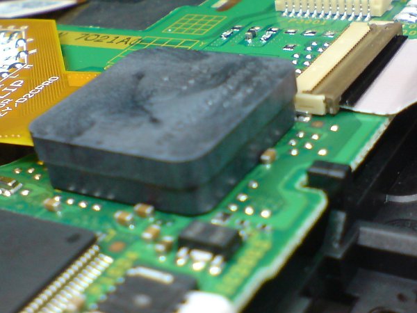


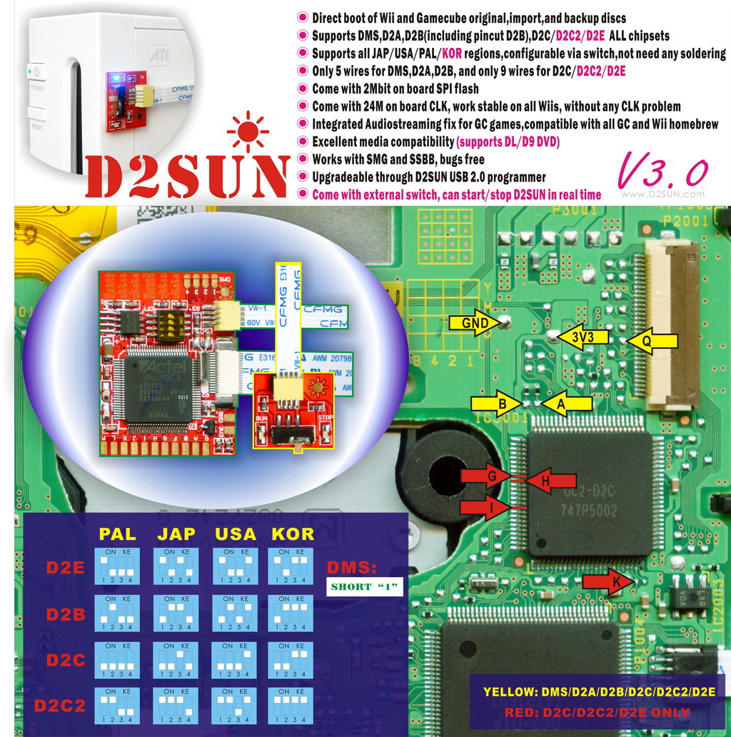
WARNING: IF YOU ATTEMPT TO PUSH THE CLIP DOWN WITHOUT SEATING THE CLIP FIRST IN IT'S PROPER POSITION YOU RUN THE RISK OF DAMAGING YOUR PINS! PLEASE READ THESE SECTIONS FIRST BEFORE ATTEMPTING TO INSTALL ANY WII-CLIP! Locate the IC chip on the underside of you DVD drive, to confirm you have a D2C chipset this particular IC should have GC2-D2C or GC2-D2E or GC2-D2B or GC2-DMS stamped on to it in gold lettering (D2C2 drives do not have D2C2 Stamped on them, they still say D2C). Make sure there is nothing obstructing the pins for the clip around the IC. |
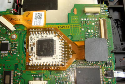
The clip and chip should cover the centre of the DVD drive, DO NOT INSTALL IT ANY OTHER WAY THAN AS SHOWN TO THE LEFT The underside and overside of the chip should be sealed so that none of the points can touch any other piece of metal and short the chip out, use the cardboard tags provided or some electrical tape to cover all the solder points Also do not tape the chips down, it should hover over the vent not seal it to allow air to flow through |
The clip should sit flush as possible to the PCB (should be touching or a 0.25mm gap), you will have to apply quite a lot of pressure to get it to do this Never try reapplying the clip if you have bent any of your pins on the underside of you clip! When you put your drive back together make sure you tuck away your cable's neatley otherwise they will catch and rock the DVDROM drive when you put it back in |
 New Products
-
 $118.92
-
 $118.92
-
 $118.92
-
 $118.92
-
 $50.92

Our Newsletter
Current Top Sellers
-
1

-
2

-
3
-
4

-
5


New Products
-
$118.92
-
$118.92
-
$118.92
-
$118.92
-
$50.92
